Toyota Corolla Cross: Installation
INSTALLATION
CAUTION / NOTICE / HINT
COMPONENTS (INSTALLATION)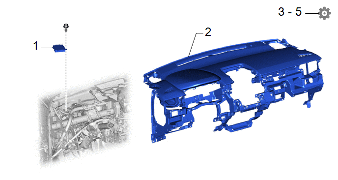
|
Procedure |
Part Name Code |
.png) |
.png) |
.png) |
|
|---|---|---|---|---|---|
|
1 |
CLEARANCE WARNING ECU ASSEMBLY |
89340A |
- |
- |
- |
|
2 |
INSTRUMENT PANEL SAFETY PAD ASSEMBLY |
- |
- |
- |
- |
|
3 |
UPDATE ECU SECURITY KEY |
- |
- |
- |
|
|
4 |
PERFORM CALIBRATION |
- |
- |
- |
|
|
5 |
INITIALIZATION AFTER RECONNECTING AUXILIARY BATTERY TERMINAL |
- |
- |
- |
|
CAUTION / NOTICE / HINT
NOTICE:
- After replacing the clearance warning ECU assembly, make sure to perform update ECU security key.
- After performing the update ECU security key procedure, make sure to perform the initialization procedure for when the cable has been disconnected and reconnected to the negative (-) auxiliary battery terminal.
PROCEDURE
1. INSTALL CLEARANCE WARNING ECU ASSEMBLY
2. INSTALL INSTRUMENT PANEL SAFETY PAD ASSEMBLY
Click here .gif)
3. UPDATE ECU SECURITY KEY
Click here
4. PERFORM CALIBRATION
Click here
5. INITIALIZATION AFTER RECONNECTING AUXILIARY BATTERY TERMINAL
HINT:
When disconnecting and reconnecting the auxiliary battery, there is an automatic learning function that completes learning when the respective system is used.
Click here


