Toyota Corolla Cross: Inspection
INSPECTION
PROCEDURE
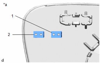
1. INSPECT OUTER MIRROR LH
(a) Check the operation of the mirror heater.
| (1) Measure the resistance according to the value(s) in the table below.
Standard Resistance: |
Tester Connection | Condition |
Specified Condition | |
1 - 2 | 25°C |
3.57 to 4.83 Ω | If the result is not as specified, replace the outer mirror LH. |
 |
|
*a | Component without harness connected
(Outer Mirror LH) | | |
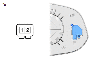
(b) Check the operation of the outer rear view mirror indicator. (w/ Blind Spot Monitor System)
(1) Connect 4 new 1.5 V dry-cell batteries in series.
| (2) Apply 6 V dry-cell batteries to the terminals of the connector, and check the blind spot monitor indicator condition.
NOTICE: Do not apply a voltage of more than 6 V. OK: |
Battery Connection | Specified Condition | |
1 - Positive (+) end of the 6 V dry-cell battery 2 - Negative (-) end of the 6 V dry-cell battery |
Blind spot monitor indicator comes on |
If the result is not as specified, replace the outer mirror LH. |
 |
|
*a | Component without harness connected
(Outer Mirror LH) | | |
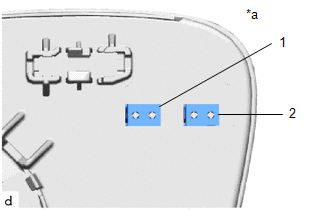
2. INSPECT OUTER MIRROR RH
(a) Check the operation of the mirror heater.
| (1) Measure the resistance according to the value(s) in the table below.
Standard Resistance: |
Tester Connection | Condition |
Specified Condition | |
1 - 2 | 25°C |
3.57 to 4.83 Ω | If the result is not as specified, replace the outer mirror RH. |
 |
|
*a | Component without harness connected
(Outer Mirror RH) | | |
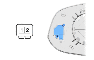
(b) Check the operation of the outer rear view mirror indicator. (w/ Blind Spot Monitor System)
(1) Connect 4 new 1.5 V dry-cell batteries in series.
| (2) Apply 6 V dry-cell batteries to the terminals of the connector, and check the blind spot monitor indicator condition.
NOTICE: Do not apply a voltage of more than 6 V. OK: |
Battery Connection | Specified Condition | |
1 - Positive (+) end of the 6 V dry-cell battery 2 - Negative (-) end of the 6 V dry-cell battery |
Blind spot monitor indicator comes on |
If the result is not as specified, replace the outer mirror RH. |
 |
|
*a | Component without harness connected
(Outer Mirror RH) | | |
READ NEXT:
INSTALLATION CAUTION / NOTICE / HINT COMPONENTS (INSTALLATION)
Procedure Part Name Code
1 OUTER MIRROR
87961
- - CAUTION / NOTICE / HINT
HINT:
PARTS LOCATION ILLUSTRATION
*1 OUTER REAR VIEW MIRROR ASSEMBLY LH
*2 OUTER REAR VIEW MIRROR ASSEMBLY RH
*3 OUTER MIRROR LH
*4 OUTER MIRROR RH
*5 OUTER MIRROR S
SEE MORE:
DESCRIPTION
Detection Item
Symptom
Trouble Area
Power Back Door ECU Communication Stop Mode
Communication stop for "Back Door" is indicated on the "Communication
Bus Check" screen of the GTS.
Click here
DESCRIPTION The air conditioning harness assembly connects the air conditioning amplifier assembly and the No. 1 air conditioning radiator damper servo sub-assembly.
The air conditioning amplifier assembly supplies power and sends operation instructions to No. 1 air conditioning radiator damper se


