Toyota Corolla Cross: Inspection
INSPECTION
PROCEDURE
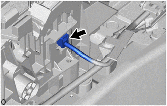
1. INSPECT SHIFT LOCK CONTROL ECU
HINT:
If the results of the following inspections are as specified but a malfunction
has occurred, replace the shift lock control unit assembly.
(a) Inspect wire harness:
|
(1) Disconnect the shift lock control ECU connector.
|
|
|
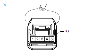
(2) Measure the voltage according to the value(s) in the table below.
Standard Voltage:
|
Tester Connection
|
Condition
|
Specified Condition
|
|
5 (IG) - Body ground
|
Ignition switch ON
|
11 to 14 V
|
|
Ignition switch off
|
Below 1 V
|
If the result is not as specified, repair or replace the shift lock control
ECU wire harness.
|
|
|
*a
|
Front view of wire harness connector
(to Shift Lock Control ECU)
|
|
|
|
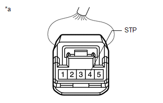
(3) Measure the voltage according to the value(s) in the table below.
Standard Voltage:
|
Tester Connection
|
Condition
|
Specified Condition
|
|
4 (STP) - Body ground
|
Ready ON, brake pedal depressed
|
11 to 14 V
|
|
Ready ON, brake pedal released
|
Below 1 V
|
If the result is not as specified, repair or replace the wire harness
or connector or replace the hybrid vehicle control ECU assembly.
|
|
|
*a
|
Front view of wire harness connector
(to Shift Lock Control ECU)
|
|
|
|
(4) Measure the resistance according to the value(s) in the table below.
Standard Resistance:
|
Tester Connection
|
Condition
|
Specified Condition
|
|
1 (E) - Body ground
|
Always
|
Below 1 Ω
|
If the result is not as specified, repair or replace the shift lock control
ECU wire harness.
|
.png) |
|
*a
|
Front view of wire harness connector
(to Shift Lock Control ECU)
|
|
|
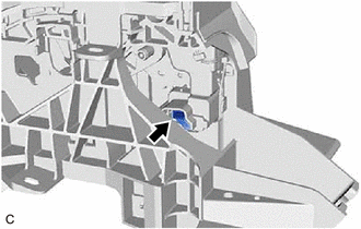
(b) Inspect shift lock solenoid:
|
(1) Disconnect the shift lock solenoid connector.
|
|
|
(2) Measure the resistance according to the value(s) in the table below.
Standard Resistance:
|
Tester Connection
|
Condition
|
Specified Condition
|
|
4 (P) - 3 (E2)
|
Shift lever in P
|
10 kΩ or higher
|
|
Shift lever not in P
|
Below 1 Ω
|
If the result is not as specified, replace the shift lock control unit
assembly.
|
.png) |
|
*a
|
Front view of wire harness connector
(to Shift Lock Solenoid)
|
|
|
|
(3) Measure the resistance according to the value(s) in the table below.
Standard Resistance:
|
Tester Connection
|
Condition
|
Specified Condition
|
|
1 (SLS+) - 2 (SLS-)
|
Always
|
112 Ω
|
If the result is not as specified, replace the shift lock control unit
assembly.
|
.png) |
|
*a
|
Front view of wire harness connector
(to Shift Lock Solenoid)
|
|
|
READ NEXT:
REASSEMBLY
CAUTION / NOTICE / HINT
COMPONENTS (REASSEMBLY)
Procedure
Part Name Code
1
SHIFT LEVER HOUSING BRACKET SUB-A
INSTALLATION
CAUTION / NOTICE / HINT
COMPONENTS (INSTALLATION)
Procedure
Part Name Code
1
TRANSMISSION FLOOR SHIFT ASSE
Removal
REMOVAL
CAUTION / NOTICE / HINT
COMPONENTS (REMOVAL)
Procedure
Part Name Code
1
SHIFT LEVER KNOB SUB-ASSEMBL
SEE MORE:
DISPOSAL CAUTION / NOTICE / HINT
CAUTION: Before performing pre-disposal deployment of any SRS part, review and closely follow all applicable environmental and hazardous material regulations. Pre-disposal deployment may be considered hazardous material treatment. PROCEDURE
1. PRECAUTION
CAUTIO
DESCRIPTION The hybrid vehicle control ECU detects a problem in the collision signal line from the airbag ECU assembly and alerts the driver.
DTC No. Detection Item
DTC Detection Condition
Trouble Area MIL
Warning Indicate Note
P310711 Lost Communication wit