Toyota Corolla Cross: Horn System
Parts Location
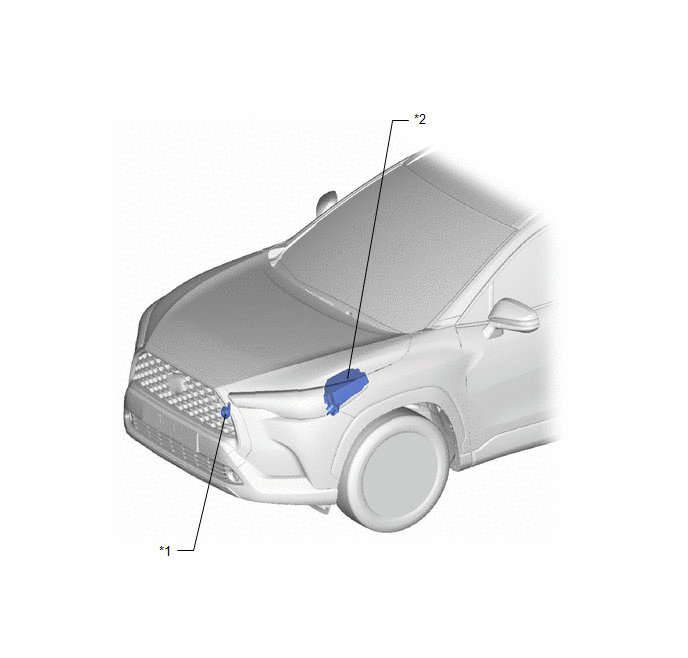
PARTS LOCATION
ILLUSTRATION
|
*1 | LOW PITCHED HORN ASSEMBLY |
*2 | NO. 1 ENGINE ROOM RELAY BLOCK ASSEMBLY - HORN FUSE - HORN RELAY ASSEMBLY |
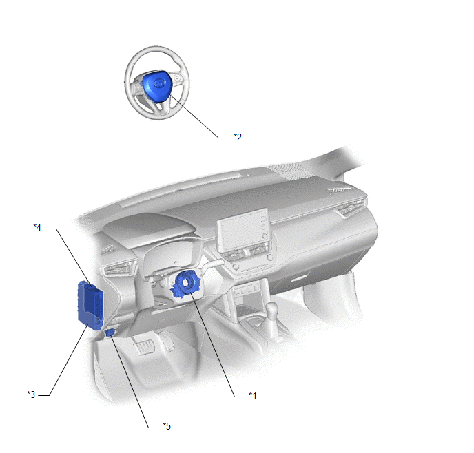
ILLUSTRATION
|
*1 | SPIRAL CABLE SUB-ASSEMBLY |
*2 | HORN BUTTON ASSEMBLY |
|
*3 | POWER DISTRIBUTION BOX ASSEMBLY |
*4 | MAIN BODY ECU (MULTIPLEX NETWORK BODY ECU) |
|
*5 | DLC3 |
- | - |
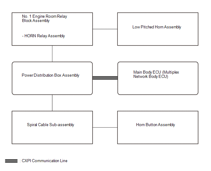
System Diagram
SYSTEM DIAGRAM
Problem Symptoms Table
PROBLEM SYMPTOMS TABLE
NOTICE:
- When replacing the power distribution box assembly, the system may not operate normally if the same part number is not used.
- Before replacing the main body ECU (multiplex network body ECU), refer to Registration.*1
- for HEV Model:
Click here
.gif)
- for Gasoline Model:
Click here
- *1: w/ Smart Key System
- for HEV Model:
HINT:
Use the table below to help determine the cause of problem symptoms. If multiple suspected areas are listed, the potential causes of the symptoms are listed in order of probability in the "Suspected Area" column of the table. Check each symptom by checking the suspected areas in the order they are listed. Replace parts as necessary.
Horn System|
Symptom | Suspected Area |
Link |
|---|---|---|
|
Horn does not sound | HORN fuse |
- |
| HORN relay assembly |
| |
|
Horn button assembly |
| |
|
Spiral cable sub-assembly |
| |
|
Power distribution box assembly |
| |
|
Harness or connector |
- | |
|
Horn sounds all the time |
HORN relay assembly |
|
|
Horn button assembly |
| |
|
Spiral cable sub-assembly |
| |
|
Power distribution box assembly |
| |
|
Main body ECU (Multiplex network body ECU) |
| |
|
Harness or connector |
- |
Data List / Active Test
DATA LIST / ACTIVE TEST
ACTIVE TEST
HINT:
Using the GTS to perform Active Tests allows relays, VSVs, actuators and other items to be operated without removing any parts. This non-intrusive functional inspection can be very useful because intermittent operation may be discovered before parts or wiring is disturbed. Performing Active Tests early in troubleshooting is one way to save diagnostic time. Data List information can be displayed while performing Active Tests.
(a) Perform the Active Test according to the display on the GTS.
Body Electrical > Main Body > Active Test|
Tester Display | Measurement Item |
Control Range | Diagnostic Note |
|---|---|---|---|
|
Vehicle Horn | Vehicle horn |
OFF or ON | - |


