Toyota Corolla Cross: Brake Switch "A" Signal Compare Failure (P057162)
DESCRIPTION
This DTC is stored when the brake signal sent via direct line and the brake signal sent via CAN communication do not match.
|
DTC No. | Detection Item |
DTC Detection Condition | Trouble Area |
Note |
|---|---|---|---|---|
| P057162 |
Brake Switch "A" Signal Compare Failure |
The brake signal sent via direct line and the brake signal sent via CAN communication do not match. (1-trip detection logic*) |
| DTC Output Confirmation Operation:
|
- *: Only detected while a malfunction is present and the ignition switch is ON.
|
Vehicle Condition when Malfunction Detected |
Fail-safe Function when Malfunction Detected |
|---|---|
| - |
|
DTC No. | Data List and Active Test |
|---|---|
|
P057162 | Power Source Control
|
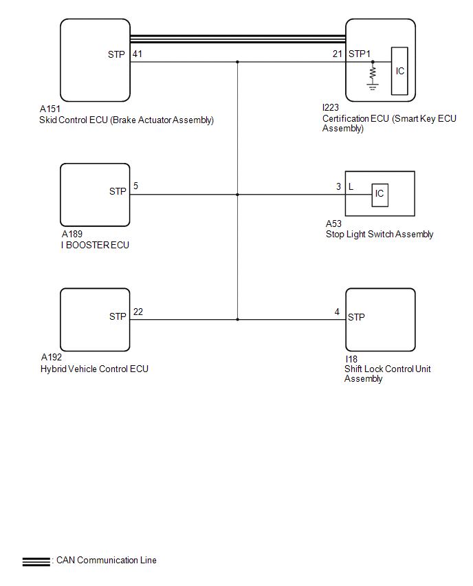
WIRING DIAGRAM
CAUTION / NOTICE / HINT
NOTICE:
- When using the GTS with the ignition switch off, connect the GTS to the DLC3 and turn a courtesy light switch on and off at intervals of 1.5 seconds or less until communication between the GTS and the vehicle begins.
Then select Model Code "KEY REGIST" under manual mode and enter the following menus: Body Electrical / Start Key(CAN). While using the GTS, periodically turn a courtesy light switch on and off at intervals of 1.5 seconds or less to maintain communication between the GTS and the vehicle.
- The smart key system (for Start Function) uses the LIN communication system and CAN communication system. Inspect the communication function by following How to Proceed with Troubleshooting. Troubleshoot the smart key system (for Start Function) after confirming that the communication systems are functioning properly.
Click here
.gif)
- When disconnecting the cable from the negative (-) auxiliary battery terminal, some systems need to be initialized after the cable is reconnected.
- Before replacing the certification ECU (smart key ECU assembly), refer to Registration.
Click here
- After repair, confirm that no DTCs are output by performing "DTC Output Confirmation Operation".
PROCEDURE
|
1. | READ VALUE USING GTS (STOP LIGHT SWITCH) |
(a) Read the Data List according to the display on the GTS.
Body Electrical > Power Source Control > Data List|
Tester Display | Measurement Item |
Range | Normal Condition |
Diagnostic Note |
|---|---|---|---|---|
|
Stop Light Switch | State of brake pedal |
OFF or ON | OFF: Brake pedal released |
|
|
Tester Display |
|---|
| Stop Light Switch |
OK:
The GTS display changes correctly in response to the brake pedal operation.
|
Result | Proceed to |
|---|---|
|
OFF is displayed | A |
|
OFF is not displayed |
B |
| B |
.gif) | GO TO STEP 3 |
|
.gif)
| 2. |
READ VALUE USING GTS (STOP LIGHT SWITCH) |
(a) Read the Data List according to the display on the GTS.
Body Electrical > Power Source Control > Data List|
Tester Display | Measurement Item |
Range | Normal Condition |
Diagnostic Note |
|---|---|---|---|---|
|
Stop Light Switch | State of brake pedal |
OFF or ON | ON: Brake pedal depressed |
|
|
Tester Display |
|---|
| Stop Light Switch |
OK:
The GTS display changes correctly in response to the brake pedal operation.
|
Result | Proceed to |
|---|---|
|
ON is displayed | A |
|
ON is not displayed | B |
| A |
| GO TO ELECTRONICALLY CONTROLLED BRAKE SYSTEM (HOW TO PROCEED WITH TROUBLESHOOTING) |
|
| 3. |
CHECK HARNESS AND CONNECTOR (CERTIFICATION ECU (SMART KEY ECU ASSEMBLY) - STOP LIGHT SWITCH ASSEMBLY) |
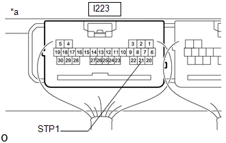
(a) Disconnect the I223 certification ECU (smart key ECU assembly) connector.
(b) Disconnect the A53 stop light switch assembly connector.
(c) Disconnect the A151 skid control ECU (brake actuator assembly) connector.
(d) Disconnect the A189 electric brake booster (brake booster with master cylinder assembly) connector.
(e) Disconnect the A192 hybrid vehicle control ECU connector.
(f) Disconnect the I18 shift lock control unit assembly connector.
(g) Measure the resistance according to the value(s) in the table below.
Standard Resistance:
|
Tester Connection | Condition |
Specified Condition |
|---|---|---|
|
I223-21 (STP1) - A53-3 (L) |
Always | Below 1 Ω |
| NG | | REPAIR OR REPLACE HARNESS OR CONNECTOR |
|
| 4. |
CHECK CERTIFICATION ECU (SMART KEY ECU ASSEMBLY) |
(a) Connect the I223 certification ECU (smart key ECU assembly) connector.
(b) Connect the A53 stop light switch assembly connector.
| (c) Measure the voltage according to the value(s) in the table below. Standard Voltage:
|
|
| OK | | REPLACE CERTIFICATION ECU (SMART KEY ECU ASSEMBLY) |
| NG | | REPLACE STOP LIGHT SWITCH ASSEMBLY |


