Toyota Corolla Cross: Brake Pressure Sensor "A" Circuit Voltage Below Threshold (C054016,C054017)
DESCRIPTION
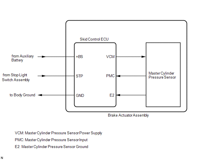
The master cylinder pressure sensor is connected to the skid control ECU inside the brake actuator assembly.
|
DTC No. |
Detection Item |
DTC Detection Condition |
Trouble Area |
MIL |
DTC Output from |
Note |
|---|---|---|---|---|---|---|
|
C054016 |
Brake Pressure Sensor "A" Circuit Voltage Below Threshold |
Divergence between relative displacement sensor value of electric brake booster (brake booster with master cylinder assembly) and oil pressure value of skid control ECU (brake actuator assembly) is large. |
Skid control ECU (brake actuator assembly) |
Comes on |
Brake/EPB |
|
|
C054017 |
Brake Pressure Sensor "A" Circuit Voltage Above Threshold |
Divergence between relative displacement sensor value of electric brake booster (brake booster with master cylinder assembly) and oil pressure value of skid control ECU (brake actuator assembly) is large. |
Skid control ECU (brake actuator assembly) |
Comes on |
Brake/EPB |
|
MONITOR DESCRIPTION
C053D (Case 1):- When the master cylinder pressure sensor and CAN communication are normal, the vehicle is being driven at a certain speed or more, and the master cylinder pressure is too high with respect to the brake pedal stroke amount as detected by the electric brake booster (brake booster with master cylinder assembly), the electric brake booster (brake booster with master cylinder assembly) illuminates the MIL and stores this DTC.
- When the master cylinder pressure sensor and CAN communication are normal, the vehicle is being driven at a certain speed or more, and the master cylinder pressure is too low with respect to the brake pedal stroke amount as detected by the electric brake booster (brake booster with master cylinder assembly), the electric brake booster (brake booster with master cylinder assembly) illuminates the MIL and stores this DTC.
MONITOR STRATEGY
|
Related DTCs |
C053D (Case 1): Pressure sensor rationality monitor (high) C053D (Case 2): Pressure sensor rationality monitor (low) |
|
Required Sensors/Components(Main) |
Electric brake booster (brake booster with master cylinder assembly) Brake pedal stroke sensor assembly |
|
Required Sensors/Components(Related) |
Electric brake booster (brake booster with master cylinder assembly) Speed sensor |
|
Frequency of Operation |
Continuous |
|
Duration |
0.2 seconds |
|
MIL Operation |
2 driving cycles |
|
Sequence of Operation |
None |
TYPICAL ENABLING CONDITIONS
|
Monitor runs whenever the following DTCs are not stored |
TMC's intellectual property |
|
Other conditions belong to TMC's intellectual property |
- |
TYPICAL MALFUNCTION THRESHOLDS
|
TMC's intellectual property |
- |
COMPONENT OPERATING RANGE
|
TMC's intellectual property |
- |
CONFIRMATION DRIVING PATTERN
NOTICE:
When performing the normal judgment procedure, make sure that the driver door is closed and is not opened at any time during the procedure.
HINT:
- After repair has been completed, clear the DTC and then check that the vehicle has returned to normal by performing the following All Readiness check procedure.
- When clearing the permanent DTCs, refer to the "CLEAR PERMANENT DTC" procedure.
- Connect the GTS to the DLC3.
- Turn the ignition switch to ON and turn the GTS on.
- Clear the DTCs (even if no DTCs are stored, perform the clear DTC procedure).
- Turn the ignition switch off.
- Turn the ignition switch to ON (READY) and turn the GTS on.
- Drive the vehicle at a speed of 3 km/h (2 mph) or more for 1 second or more. [*1]
- Enter dealer mode or inspection mode, and drive the vehicle at a speed
of 10 km/h (6 mph) for 1 second or more. [*2]
HINT:
[*1] to [*2]: Normal judgment procedure.
The normal judgment procedure is used to complete DTC judgment and also used when clearing permanent DTCs.
- Enter the following menus: Chassis / Brake Booster / Utility / All Readiness.
- Check the DTC judgment result.
HINT:
- If the judgment result shows NORMAL, the system is normal.
- If the judgment result shows ABNORMAL, the system has a malfunction.
- If the judgment result shows INCOMPLETE, perform driving pattern again.
PROCEDURE
|
1. |
CLEAR DTC |
(a) Clear the DTCs.
Chassis > Brake/EPB > Clear DTCs(b) Turn the ignition switch off.
|
.gif)
|
2. |
RECONFIRM DTC |
(a) Based on the Freeze Frame Data and interview with the customer, attempt to reproduce the conditions when the malfunction occurred.
(b) Check if the same DTC is output.
Chassis > Brake/EPB > Trouble Codes|
Result |
Proceed to |
|---|---|
|
C054016 and C054017 are not output |
A |
|
C054016 and/or C054017 are output |
B |
| A | .gif)
|
USE SIMULATION METHOD TO CHECK |
| B |
|
REPLACE BRAKE ACTUATOR ASSEMBLY |
READ NEXT:
 Brake Pressure Sensor "A" Circuit Voltage Out of Range (C05401C,...,C054096)
DESCRIPTION
Refer to DTC C054016
Click here
DTC No.
Detection Item
DTC Detection Condition
Trouble Area
MIL
DTC Output from
Left Front Wheel Speed Sensor Incorrect Component Installed (C055595)
DESCRIPTION
DTC No.
Detection Item
DTC Detection Condition
Trouble Area
MIL
DTC Output from
Note
C055595
Right Front Wheel Speed Sensor Incorrect Component Installed (C055695)
DESCRIPTION
DTC No.
Detection Item
DTC Detection Condition
Trouble Area
MIL
DTC Output from
Note
C055695
SEE MORE:
 Installation
INSTALLATION
CAUTION / NOTICE / HINT
COMPONENTS (INSTALLATION)
Procedure
Part Name Code
1
BRAKE PEDAL PAD
47121
-
-
-
2
WIRING HARNESS CONNECTOR
Parts Location
PARTS LOCATION
ILLUSTRATION
*A
w/ Sliding Roof System
-
-
*1
FRONT POWER WINDOW REGULATOR MOTOR ASSEMBLY (DRIVER DOOR)
*2
FRONT POWER WINDOW REGULATOR MOTOR ASSEMBLY (FRONT PASSENGER DOOR)
