Toyota Corolla Cross: Brake Pedal Position Sensor Supply Voltage Circuit Voltage Out of Range (C05621C,...,P157A62)
DESCRIPTION
The brake pedal stroke sensor assembly sends the brake pedal stroke distance to the skid control ECU inside the brake actuator assembly.
|
DTC No. |
Detection Item |
DTC Detection Condition |
Trouble Area |
MIL |
DTC Output from |
Note |
|---|---|---|---|---|---|---|
|
C05621C |
Brake Pedal Position Sensor Supply Voltage Circuit Voltage Out of Range |
Brake pedal stroke sensor assembly power source malfunction detected. |
|
Does not come on |
Brake/EPB |
Output ECU: Skid control ECU (brake actuator assembly) |
|
C139200 |
Zero Point Calibration of Stroke Sensor |
While the brake pedal is not being depressed, brake pedal stroke sensor assembly zero point not calibrated signal is received. (A correct brake pedal stroke sensor assembly zero point learning value is not present). |
|
Does not come on |
Brake/EPB |
Output ECU: Skid control ECU (brake actuator assembly) |
|
P057A11 |
Brake Pedal Position Sensor "A" Circuit Short to Ground |
Open or short detected due to abnormality in brake pedal stroke sensor assembly output circuit 1. |
|
Does not come on |
Brake/EPB |
Output ECU: Skid control ECU (brake actuator assembly) |
|
P057A15 |
Brake Pedal Position Sensor "A" Circuit Short to Battery or Open |
Open or short detected due to abnormality in brake pedal stroke sensor assembly output circuit 1. |
|
Does not come on |
Brake/EPB |
Output ECU: Skid control ECU (brake actuator assembly) |
|
P057A28 |
Brake Pedal Position Sensor "A" Signal Bias Level Out of Range / Zero Adjustment Failure |
Difference in change amount of brake pedal stroke sensor assembly output voltage 1 (SKS1) is abnormally large for 0.1 seconds or more. (SKS1 output comparison invalid). |
|
Does not come on |
Brake/EPB |
Output ECU: Skid control ECU (brake actuator assembly) |
|
P057A64 |
Brake Pedal Position Sensor "A" Signal Plausibility Failure |
Difference in change amount of brake pedal stroke sensor assembly output voltage 1 (SKS1) is abnormally large for 0.2 seconds or more. (SKS1 output comparison invalid). |
|
Does not come on |
Brake/EPB |
Output ECU: Skid control ECU (brake actuator assembly) |
|
P05DB11 |
Brake Pedal Position Sensor "B" Circuit Short to Ground |
Open or short detected due to abnormality in brake pedal stroke sensor assembly output circuit 2. |
|
Does not come on |
Brake/EPB |
Output ECU: Skid control ECU (brake actuator assembly) |
|
P05DB15 |
Brake Pedal Position Sensor "B" Circuit Short to Battery or Open |
Open or short detected due to abnormality in brake pedal stroke sensor assembly output circuit 2. |
|
Does not come on |
Brake/EPB |
Output ECU: Skid control ECU (brake actuator assembly) |
|
P05DB28 |
Brake Pedal Position Sensor "B" Signal Bias Level Out of Range / Zero Adjustment Failure |
Difference in change amount of brake pedal stroke sensor assembly output voltage 2 (SKS2) is abnormally large for 0.1 seconds or more. (SKS2 output comparison invalid). |
|
Does not come on |
Brake/EPB |
Output ECU: Skid control ECU (brake actuator assembly) |
|
P05DB64 |
Brake Pedal Position Sensor "B" Signal Plausibility Failure |
Difference in change amount of brake pedal stroke sensor assembly output voltage 2 (SKS2) is abnormally large for 0.2 seconds or more. (SKS2 output comparison invalid). |
|
Does not come on |
Brake/EPB |
Output ECU: Skid control ECU (brake actuator assembly) |
|
P05E064 |
Brake Pedal Position Sensor "A"/"B" Signal Plausibility Failure |
Difference between change amounts of brake pedal stroke sensor assembly output voltage 1 (SKS1) and brake pedal stroke sensor assembly output voltage 2 (SKS2) is abnormally large for 0.2 seconds or more. (SKS1 and SKS2 output comparison invalid). |
|
Does not come on |
Brake/EPB |
Output ECU: Skid control ECU (brake actuator assembly) |
|
P157A62 |
Brake Pedal Position Sensor "A" / "B" Brake Master Cylinder Pressure Sensor Multiple Sensor Signal Compare Failure |
While driving at a vehicle speed of 3 km/h or more, the master cylinder pressure sensor value is too high relative to the brake pedal stroke sensor assembly value for 0.2 seconds or more. |
|
Does not come on |
Brake/EPB |
Output ECU: Skid control ECU (brake actuator assembly) |
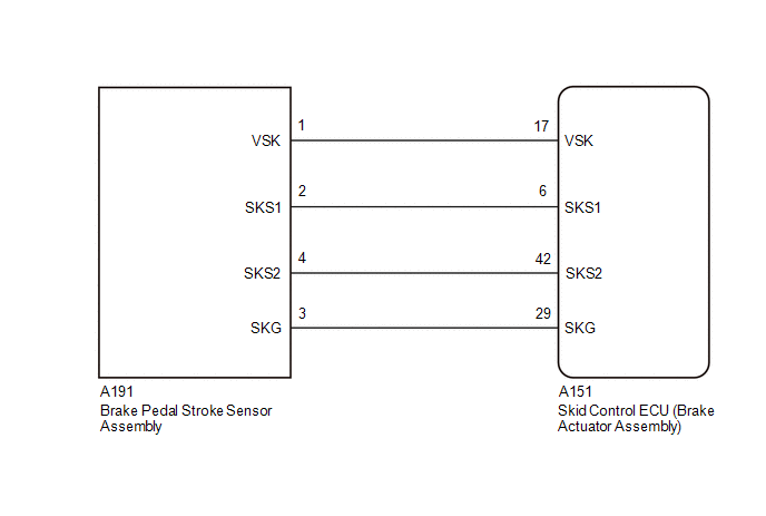
WIRING DIAGRAM
PROCEDURE
|
1. |
CHECK BRAKE PEDAL |
(a) Check that the brake pedal and the brake pedal stroke sensor assembly are properly installed and that the pedal can be depressed normally.
(b) Check and adjust the brake pedal height.
Click here .gif)
(c) Adjust the brake pedal stroke sensor assembly.
Click here
|
.gif)
|
2. |
CHECK DTC |
(a) Read the DTCs using the GTS.
Chassis > Brake/EPB > Trouble Codes|
Result |
Proceed to |
|---|---|
|
C05621C, C139200, P057A11, P057A15, P057A28, P057A64, P05DB11, P05DB15, P05DB28, P05DB64, P05E064 or P157A62 is output |
A |
|
Only C139200 is output |
B |
|
None of the above conditions are met |
C |
| B | .gif)
|
GO TO STEP 5 |
| C |
|
REPAIR CIRCUITS INDICATED BY OUTPUT DTCS |
|
|
3. |
CHECK HARNESS AND CONNECTOR (BRAKE ACTUATOR ASSEMBLY - BRAKE PEDAL STROKE SENSOR ASSEMBLY) |
(a) Turn the ignition switch off.
(b) Make sure that there is no looseness at the locking part and the connecting part of the connectors.
OK:
The connector is securely connected.
(c) Disconnect the A151 skid control ECU (Brake Actuator Assembly) connector.
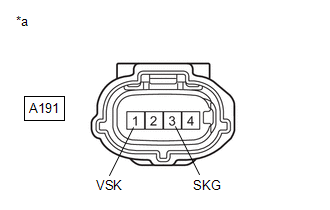
(d) Disconnect the A191 brake pedal stroke sensor assembly connector.
(e) Check both the connector case and the terminals for deformation and corrosion.
OK:
No deformation or corrosion.
(f) Measure the resistance according to the value(s) in the table below.
Standard Resistance:
|
Tester Connection |
Condition |
Specified Condition |
|---|---|---|
|
A151-17 (VSK) - A191-1 (VSK) |
Always |
Below 1 Ω |
|
A151-17 (VSK) or A191-1 (VSK) - Body ground |
Always |
10 kΩ or higher |
|
A151-6 (SKS1) - A191-2 (SKS1) |
Always |
Below 1 Ω |
|
A151-6 (SKS1) or A191-2 (SKS1) - Body ground |
Always |
10 kΩ or higher |
|
A151-42 (SKS2) - A191-4 (SKS2) |
Always |
Below 1 Ω |
|
A151-42 (SKS2) or A191-4 (SKS2) - Body ground |
Always |
10 kΩ or higher |
|
A151-29 (SKG) - A191-3 (SKG) |
Always |
Below 1 Ω |
|
A151-29 (SKG) or A191-3 (SKG) - Body ground |
Always |
10 kΩ or higher |
| NG |
|
REPAIR OR REPLACE HARNESS OR CONNECTOR |
|
|
4. |
INSPECT BRAKE ACTUATOR ASSEMBLY (SENSOR OUTPUT) |
|
(a) Make sure that there is no looseness at the locking part and the connecting part of the connectors. OK: The connector is securely connected. |
|
(b) Disconnect the A191 brake pedal stroke sensor assembly connector.
(c) Check both the connector case and the terminals for deformation and corrosion.
OK:
No deformation or corrosion.
(d) Turn the ignition switch to ON.
(e) Measure the voltage according to the value(s) in the table below.
Standard Voltage:
|
Tester Connection |
Condition |
Specified Condition |
|---|---|---|
|
A191-1 (VSK) - A191-3 (SKG) |
Ignition switch ON |
4.84 to 5.16 V |
| OK |
|
REPLACE BRAKE PEDAL STROKE SENSOR ASSEMBLY |
| NG |
|
REPLACE BRAKE ACTUATOR ASSEMBLY |
|
5. |
CLEAR BRAKE PEDAL STROKE SENSOR ASSEMBLY ZERO POINT |
(a) Using the GTS, clear the brake pedal stroke sensor assembly zero point.
Chassis > Brake/EPB > Utility|
Tester Display |
|---|
|
Reset Memory |
|
|
6. |
PERFORM BRAKE PEDAL STROKE SENSOR ASSEMBLY ZERO POINT CALIBRATION |
(a) Using the GTS, perform the brake pedal stroke sensor assembly zero point calibration.
Chassis > Brake/EPB > Utility|
Tester Display |
|---|
|
Calibration |
|
|
7. |
CLEAR DTC |
(a) Clear the DTCs.
Chassis > Brake/EPB > Clear DTCs(b) Turn the ignition switch off.
|
|
8. |
RECONFIRM DTC |
(a) Based on the Freeze Frame Data and interview with the customer, attempt to reproduce the conditions when the malfunction occurred.
(b) Check if the same DTC is output.
Chassis > Brake/EPB > Trouble Codes|
Result |
Proceed to |
|---|---|
|
C139200 is output |
A |
|
DTCs are not output |
B |
|
None of the above conditions are met |
C |
| B |
|
USE SIMULATION METHOD TO CHECK |
| C |
|
REPAIR CIRCUITS INDICATED BY OUTPUT DTCS |
|
|
9. |
INSPECT BRAKE ACTUATOR ASSEMBLY (SENSOR OUTPUT) |
|
(a) Turn the ignition switch off. |
|
(b) Make sure that there is no looseness at the locking part and the connecting part of the connectors.
OK:
The connector is securely connected.
(c) Reconnect the A191 brake pedal stroke sensor assembly connector.
(d) Check both the connector case and the terminals for deformation and corrosion.
OK:
No deformation or corrosion.
(e) Turn the ignition switch to ON.
(f) Measure the voltage according to the value(s) in the table below.
Standard Voltage:
|
Tester Connection |
Condition |
Specified Condition |
|---|---|---|
|
A191-1 (VSK) - A191-3 (SKG) |
Ignition switch ON |
4.84 to 5.16 V |
| OK |
|
REPLACE BRAKE PEDAL STROKE SENSOR ASSEMBLY |
| NG |
|
REPLACE BRAKE ACTUATOR ASSEMBLY |
READ NEXT:
 Brake System Control Module "A" System Internal Failure (C059704)
DESCRIPTION
The skid control ECU (brake actuator assembly) stores this DTC
if malfunctions are found in a circuit inside the ECU by self-diagnosis.
DTC No.
Detection Item
Brake System Control Module "A" Calibration / Parameter Memory Failure (C059746)
DESCRIPTION
If the system information stored by the skid control ECU (brake
actuator assembly) is corrupted, this DTC is output.
DTC No.
Detection Item
DTC Detecti
ABS Operation Continuous Request (C116E63,C116F63,C124E62)
DESCRIPTION
The skid control ECU (brake actuator assembly) measures the
speed of each wheel by receiving signals from each speed sensor.
These signals are used for recognizing that all four wheels
SEE MORE:
 Adjustment
ADJUSTMENT
PROCEDURE
1. INSPECT AND ADJUST BRAKE PEDAL HEIGHT
(a) Remove the front door scuff plate LH.
Click here
(b) Remove the cowl side trim sub-assembly LH.
Click here
(c) Turn back the front floor carpet assembly.
(d) Check the brake pedal height.
NOTICE:
Inspect and adjust th
A/C Inverter High Voltage Output Circuit Voltage Out of Range (B14721C)
DESCRIPTION The inverter in the compressor with motor assembly outputs high-voltage electricity to operate the motor. If there is an open or short in the output circuit, the hybrid vehicle control ECU will stop compressor operation and store this DTC. This DTC will be stored as a history DTC. The co
